Call Anytime
Building with Earthwise SIPs
While many projects involve the expertise of an architect or design professional, it's crucial for SIP installers to have a solid grasp of the fundamental design and engineering principles governing SIP construction. It's worth noting that these details serve an informational purpose only.
When embarking on a SIP building project, always refer to the panel layout drawings included with the SIP package for specific connection methods and fastening schedules. These panel layout drawings are often tailored to the unique requirements of the project and engineered to meet design loads that can vary depending on factors such as location, building type, and local building codes.
Following are some key definitions to keep in mind when working with SIPs.
- Spline: A piece of dimensional lumber, engineered wood, or other specialized material used to connect two panels together at in-plane vertical panel connections.
- Cap plate: Dimensional lumber that has been cut to match the full width of a SIP wall panel, serving the purpose of transferring in-plane loads to the structural facings.
- Panel screws or SIP screws: Specialty screws designed for fastening through the thickness of a SIP.
- Capillary break: Treated plywood or another suitable material placed over concrete to prevent SIP facings from absorbing moisture.
- Fascia: A visible horizontal band running along the roof edge, typically used to cap the tails of roof rafters.

Starting a SIP Project
Before commencing construction on a SIP project, several important considerations must be addressed during the design phase.
Is SIP the Right Choice for Your Project?
Depending on the nature of the project, the designer or builder must evaluate whether Structural Insulated Panels (SIPs) are the optimal choice for walls, roofs, or floors. SIP floors are typically reserved for scenarios where the underside of the floor is fully exposed to the elements, as seen in homes constructed on pilings.
SIP walls, on the other hand, can be employed in virtually any situation suitable for wood frame construction. They offer enhanced strength compared to conventional wood frame walls, and their generous sizes provide various advantages in terms of design and installation.
The decision regarding SIP roof usage hinges on the roof design and the feasibility of incorporating a supporting structure. Certain architectural styles, such as craftsman-style homes, timber frames, Cape Cods, or A-frames, lend themselves well to SIPs, particularly for framing and insulating vaulted ceilings. In many instances, roof trusses may align better with the home's design than a SIP roof system. Hybrid systems, such as SIP walls combined with a truss roof or a SIP roof atop insulated concrete form (ICF) walls, are common approaches to creating high-performance homes.
- Do You Require a SIP Designer?
When working with pre-existing home plans or construction documents initially intended for conventional wood framing, these drawings must be adapted for SIP construction. Typically, this task falls to trained SIP design professionals or is a service offered by a SIP provider. The builder, client, and architect (if involved) will collaborate to review the SIP designs, ensuring alignment with the original construction documents.
Completed SIP layout drawings encompass all critical information essential for SIP package installation. In contrast to architectural drawings or construction documents, SIP layout drawings exclusively focus on the SIP building envelope and other structural elements necessary for SIP installation.
Is an Engineer Necessary?
It's advisable to consult with an engineer to determine whether additional structural engineering is required for your specific SIP project.
SIP Floors Details
When opting for SIP floors, the SIP designer will determine the suitable panel thickness based on the span required for the floor panel. Additionally, they will craft a foundation connection detail (refer to diagram below) to ensure proper bearing on the foundation system. This detail serves a dual purpose by safeguarding against moisture intrusion through effective air infiltration sealing and incorporating a capillary break of treated material between the SIP and any concrete surfaces.
Point loads represent a crucial consideration when it comes to SIP floors. If a soft floor covering such as vinyl or carpet is specified, it's customary to add a second layer of floor sheathing over the SIP floor. Point loads within the wall system can also pose concerns over SIP floors, potentially necessitating blocking or direct support from the foundation.

SIP Wall Details
The responsibility of determining SIP wall thickness typically falls within the designer's domain. The selection of wall thickness involves a delicate balance between insulating capacity and structural performance, where thicker SIP walls offer increased thermal resistance (measured by R-value) and greater resistance to lateral loads. Given that a significant portion of energy efficiency in SIP buildings stems from airtightness, it is advisable for designers to contemplate comprehensive whole-building energy modeling when establishing the requisite R-value for SIP walls.
Foundation Connection
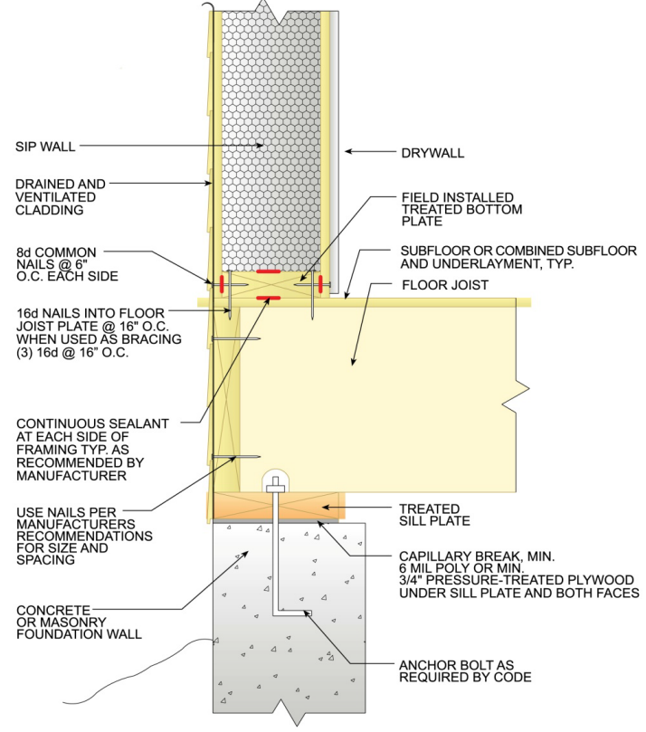
SIP walls can be supported in two primary ways: atop a platform-framed floor system or directly on the foundation. Platform-framed floor systems sometimes introduce air leakage concerns, making SIP walls designed to bear directly on the foundation a preferred choice for enhanced airtightness. However, this approach necessitates a wider foundation with relatively precise tolerances.
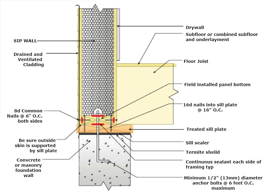
In cases where SIP walls rest directly on a concrete foundation or concrete slab, it is essential to include a capillary break comprising treated plywood or treated lumber beneath the SIP wall. This crucial measure acts as a safeguard against moisture infiltration.
SIP wall on wood frame floor system

SIP wall resting on foundation

Corner Connection
Where two SIP walls intersect at a right angle, dimensional lumber end plates are introduced into the foam recesses of both walls (as illustrated below). These walls are subsequently fastened together using panel screws. It's essential to bear in mind that this particular lap detail results in one of the walls being slightly shorter than the overall building dimensions.
SIP wall corner detail

Interior Walls
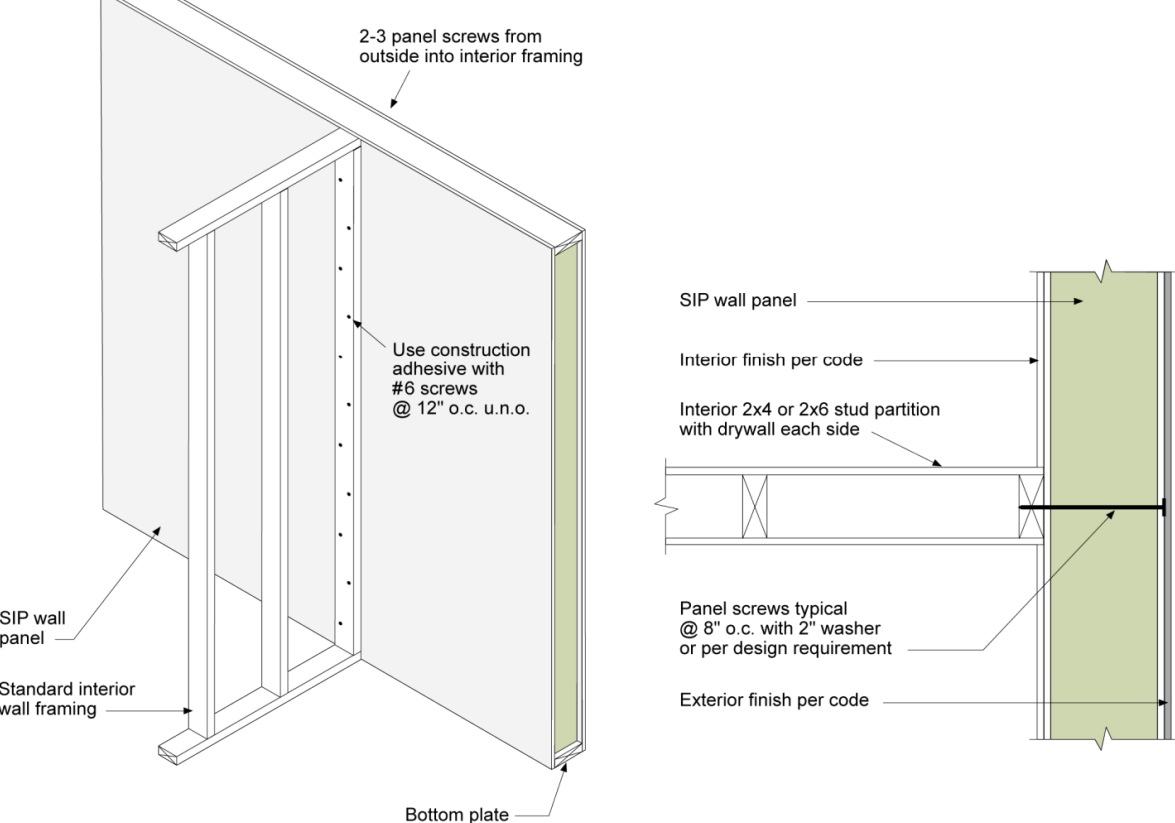
For affixing interior partitions to SIPs, a staggered screw pattern is employed on the interior, supplemented by panel screws inserted from the exterior (as shown below). This dual-screw method, spanning the thickness of the panel, effectively prevents any potential shifting that might lead to drywall cracks.
Spline Connections
Spline joints are employed for connecting panels in the same plane, applicable to both wall and roof panels. Within a SIP layout drawing, spline connection details also indicate the precise locations where sealant must be applied to establish an airtight seal. The sealing process stands as one of the pivotal elements in SIP installation. Panels that are not sealed correctly can give rise to issues like moisture damage, mold, rot, and even structural failure.
Surface Spline
A surface spline connection, as illustrated below, comprises two strips crafted from OSB or plywood. These strips are inserted into pre-made slots within the foam core of the SIP. Subsequently, they are securely fastened by nails driven through both faces of the panel, establishing a reliable connection. One notable benefit of this panel connection method is its ability to circumvent the thermal bridging issues that can arise with lumber connections.

Block Spline
The block spline, as depicted below, operates in a manner similar to the surface spline. However, it employs a solitary spline composed of a foam core enclosed by OSB or plywood facings. This spline is affixed in position by nails driven through the panel's facings and, akin to the surface spline, effectively mitigates thermal bridging across the panel joint.

Double Dimensional Lumber Spline
In specific scenarios, there may be a need for a dimensional lumber connection, as depicted below, to enhance transverse load resistance or accommodate a point load within a SIP wall. Such lumber connections can involve the use of single-dimensional lumber, double-dimensional lumber, or engineered wood products like laminated veneer lumber (LVL). It's important to note that dimensional lumber splines introduce a thermal bridge and have the potential to become a source of air leakage if the joint is not adequately sealed.

I-Joist Spline
The I-joist spline connection, as depicted below, employs an engineered wood I-joist, akin to those typically utilized for residential construction floor joists. The I-joist reinforces the panel connection while offering the advantage of being considerably lighter than dimensional lumber, making it easier to handle on the construction site. Moreover, due to their status as engineered lumber products, I-joists exhibit greater straightness and ease of installation compared to sawn lumber.
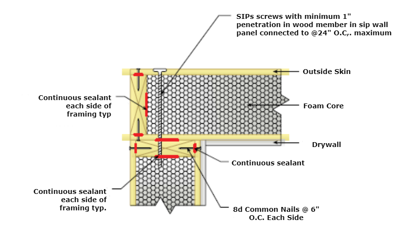
Intermediate Floor Specifics
In the context of constructing with SIP walls, you have the choice between framing intermediate floors using either platform framing or a hanging floor system. Platform framing, a technique widely used in conventional wood construction, entails positioning floor joists directly atop the SIP wall panel, as illustrated below. Depending on the expected loading conditions, there may be a need for a cap plate, custom-cut to match the full width of the SIP wall panel. This cap plate is then affixed above the top plate, ensuring that the floor joists receive complete support from both the inner and outer facings of the SIP wall.
Intermediate platform-framed floor

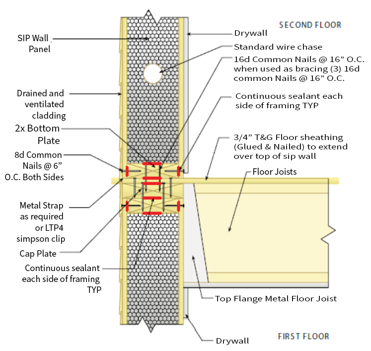
An alternative approach for intermediate floors involves employing a hanging floor system, as illustrated below. This method incorporates a top-mounted joist hanger fastened to the upper portion of the first-floor wall. Hanging floors are often preferred for their enhanced energy efficiency, as they effectively eliminate the possibility of air leakage through the floor system or rim joist area.
Intermediate hanging floor

Connecting Walls to Roofs with SIPs
The connection between walls and roofs can be established using either a bevel-cut SIP wall or a square-cut SIP wall, contingent on factors such as roof pitch, roof system type, and the Earthwise preference.
In a bevel-cut approach, the SIP wall has been precisely cut to match the pitch of the roof. Top plates are inserted into the foam recess at the upper section of the wall panels, serving both as support and as recipients for the panel screws used to affix the SIP roof system.
Alternatively, when a SIP roof is situated atop a square-cut SIP wall, framing teams must introduce bevel-cut solid lumber at the wall's uppermost section to align with the roof pitch and provide adequate bearing for the roof panels. Regardless of the chosen method, it is essential to recognize that the wall-to-roof connection constitutes a pivotal sealing area in the construction process.
Bevel-cut SIP wall detail

It's customary to employ conventional truss roofs atop SIP walls. In such instances, a square-cut SIP wall is utilized, accompanied by a cap plate custom-cut to match the full width of the SIP wall panel. The incorporation of the cap plate enhances the axial load-bearing capability of the SIP wall system by evenly dispersing the point loads generated by the trusses across both the inner and outer facings of the SIP wall system.
Square-cut SIP wall detail

Other Engineering Considerations for SIP walls
Headers
In numerous instances, window and door openings within SIP walls can be created without the necessity for a structural header. Opting to forego structural headers whenever feasible not only reduces thermal bridging but also streamlines the construction process. SIP manufacturers have conducted extensive testing and released load tables specifying the maximum permissible spans for door and window openings without requiring the addition of a structural header. These determinations factor in the opening's width and the structural forces exerted on the wall.
In cases where these prescribed limits are exceeded, designers will prescribe structural wood headers, which can be constructed from dimensional lumber, engineered wood products, or even pre-manufactured insulated headers. These headers are adequately supported by posts or dimensional lumber that are integrated into the SIP wall panels on both sides of the opening.

Point Loads
Headers become a necessity whenever there is a point load situated above an opening. Point loads represent a significant focal point for SIP designers, particularly when devising a SIP roof system that relies on substantial beams or purlins for support. To address point loads, strategies must be implemented to facilitate the transfer of these loads from the roof to the foundation. This can involve embedding posts within SIP walls, incorporating a cap plate to assist in distributing the load across the SIP facings, or devising load-bearing scenarios that can be efficiently managed by the SIP wall system in isolation.
SIP Roof Design Particulars
A pivotal decision undertaken by the SIP designer revolves around the selection of roof panel thickness. Thicker SIPs offer superior R-values and can span more extensive distances. In determining the appropriate panel thickness, the designer must take into account various factors, including the overall design loads, comprehensive whole-building energy modeling, the required span distance, and the project budget.
When addressing roof spans, designers must also evaluate the type of spline connections utilized between the roof panels. While dimensional lumber or engineered lumber splines enable panels to span greater distances, it's essential to acknowledge that these products introduce a thermal bridge, potentially impacting energy efficiency and project costs.
Multiple options exist for supporting a SIP roof, with ridge beams, purlin beams, and load-bearing walls being common components in designing a system that effectively upholds the SIP roof panels and aligns with the building owner's interior space requirements.
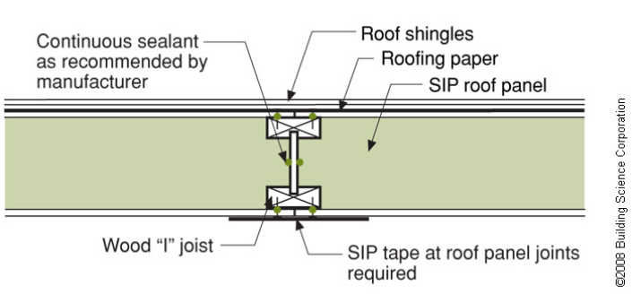
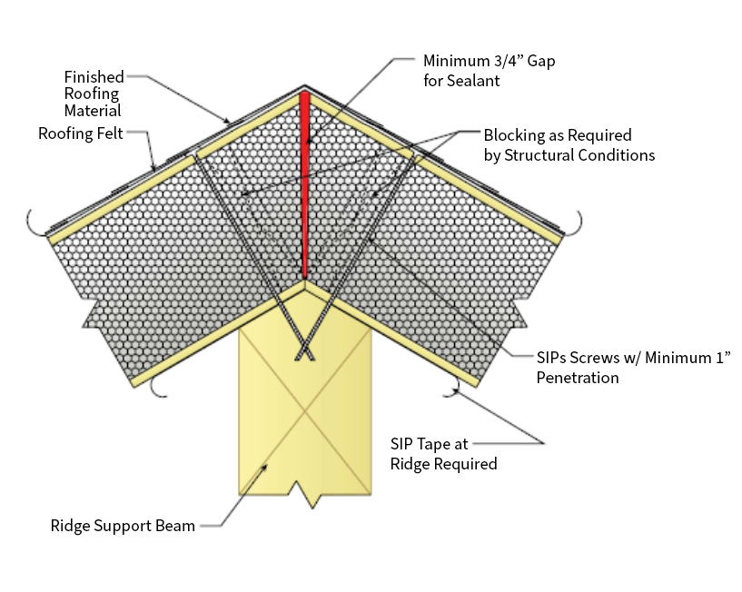
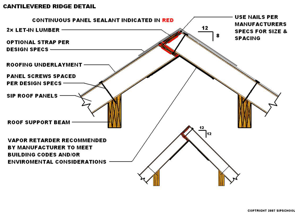
Ridge Design
A frequently employed detail in SIP roof design involves the merging of two panels over a ridge beam at the roof peak. Roof panels are securely fastened to the ridge beam using panel screws. This region is another critical point for air sealing, and many Earthwise recommends the use of specialized SIP tape in conjunction with expanding foam or mastic sealant to ensure proper sealing.

An alternative approach incorporates two purlin beams, strategically positioned away from the roof peak (as shown below). This offset ridge arrangement facilitates the creation of a false ceiling beneath the ridge, providing a dedicated space for mechanical or electrical routing.
Offset ridge detail
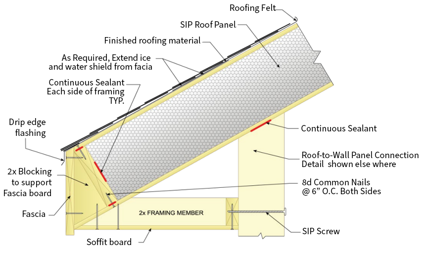
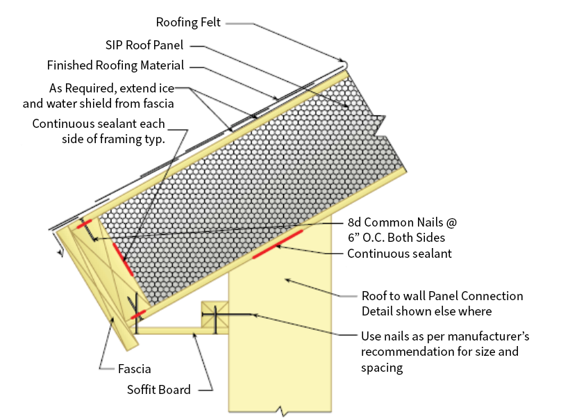
Fascia
Designers' concerns extend beyond structural aspects. From an aesthetic perspective, one distinctive consideration in SIP roof systems is the approach to finishing the roof overhang. In instances where plumb cut roof panels are used, they generate a thicker fascia height exceeding the thickness of the SIP roof panel. Conversely, by maintaining square-cut roof panels, overhangs can be framed in a manner that allows for the creation of various visually appealing designs.
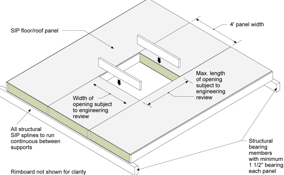
Skylights and Roof Penetrations
SIP designers must exercise meticulous consideration when determining the placement of roof penetrations. In instances where the design incorporates skylights, it becomes imperative to pinpoint their precise location and size during the design phase. This meticulous planning is essential because sizable openings can significantly impact the structural capacity of SIP roof panels. For smaller penetrations like plumbing vents, it is advisable to consolidate them to minimize the number of penetrations required through the SIP roof panels. Moreover, it is imperative that penetrations are never cut through panel splines and are always diligently sealed to prevent both air leakage and water intrusion.
Skylight in a SIP roof
Challenging Engineering Scenarios
Certain geographical areas across the country are subjected to extreme conditions such as high wind loads, heavy snow loads, or seismic activity, necessitating additional design deliberations for SIP structures. SIPs remain a feasible choice for nearly all scenarios where conventional wood framing is employed, provided that the structure undergoes thorough and appropriate design and engineering processes. The intricacies of these techniques extend beyond the scope of this book. Therefore, if you find yourself constructing within one of these regions, it is advisable to collaborate closely with you Earthwise Manufacturing and building code authorities to ascertain the specific design requisites.